
Advanced Ceramics Applications for Demanding Industrial Systems
Ceramic Components for Industrial Applications
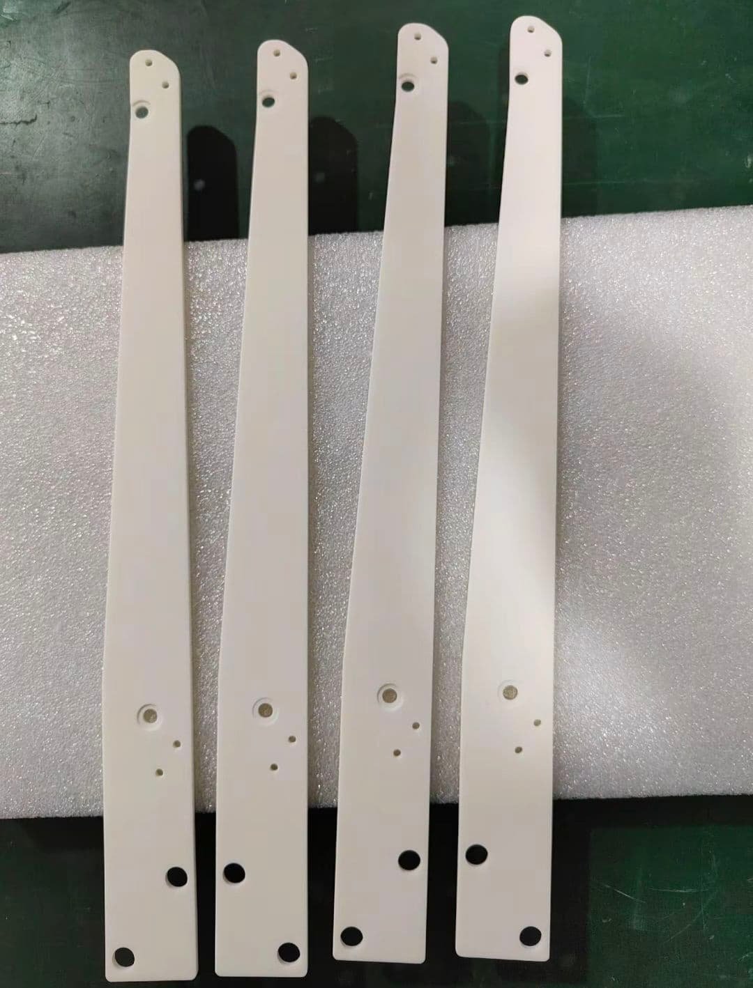
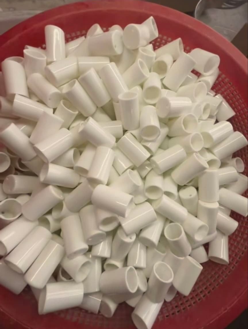
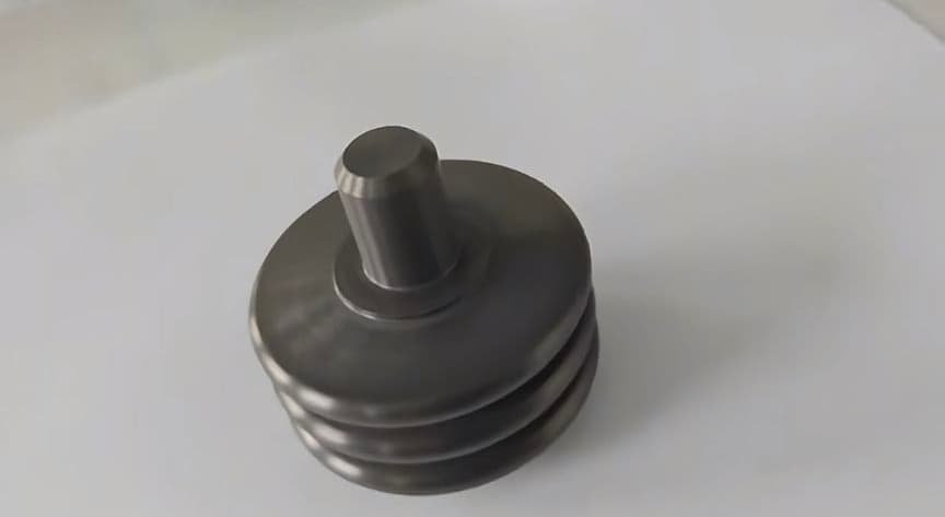
C-CERAMIC Manufacturing Capabilities
C-CERAMIC exists to help industrial teams turn demanding ceramic part requirements into production-ready components. Our ceramic manufacturing capabilities bring material and design review, mold making, forming, high-temperature sintering, machining, finishing and inspection into one coordinated engineering workflow.
From silicon carbide, zirconia, alumina and silicon nitride components to project-specific technical ceramic selections, we support prototypes, low-volume runs and scalable production. Our platform includes ceramic injection molding, precision grinding, lapping, CNC ceramic machining and final dimensional inspection for parts built around real operating conditions.
What differentiates C-CERAMIC is continuity from the first drawing through contract manufacturing. Engineering, process selection and finishing are aligned around the same component requirements, helping OEM, R&D and procurement teams source pins, seals, plates, tubes, nozzles and other custom ceramic parts with a clear path to production.
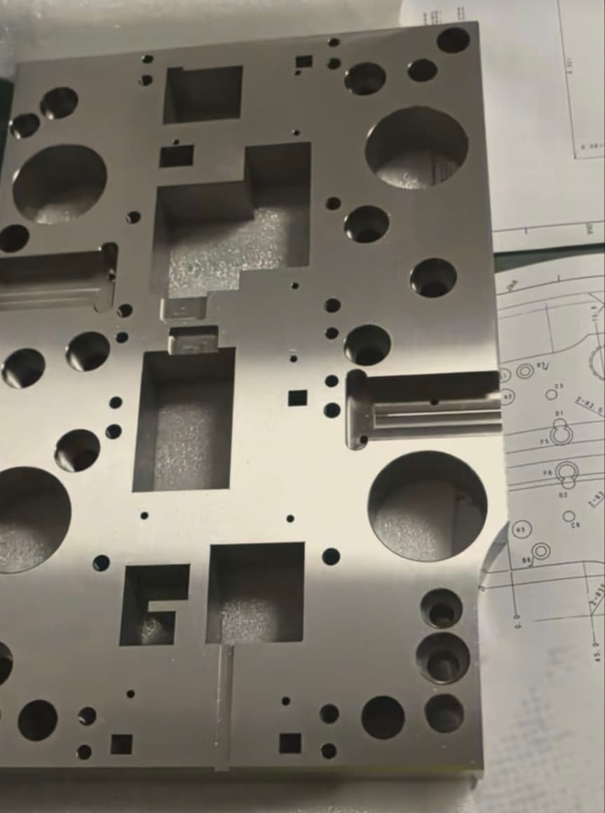
A Practical Guide to Sourcing Ceramic Solutions by Industry
Define the Industry Application and Operating Duty
Start by identifying where the ceramic component sits in the system and what it must do. Describe whether it guides, insulates, seals, supports, handles fluid, resists wear, or maintains a controlled interface. Record temperature exposure, cycling, pressure, media, contact materials, motion, loading, cleanliness expectations and the consequences of failure. Specify thermal, vacuum, chemical, electrical or mechanical conditions only when they apply to the actual component. Separate verified requirements from early design targets. Attach the drawing, assembly view and any available 3D model, highlighting datums, sealing faces, holes, threads, slots, thin sections and inaccessible features. State annual quantity, batch pattern, prototype needs and whether the part is a direct replacement or a new design. Identify any application-specific handling, contamination or packaging constraints that could affect release. This context helps determine whether a material and process recommendation is meaningful. It also prevents a visually similar ceramic component from being quoted without understanding its actual application, interfaces or inspection burden. A clear duty definition gives engineering and procurement a shared basis for comparing material families, manufacturing routes and quotation assumptions without treating generic industry language as proof of suitability.
Choose Materials and Compatible Interfaces
Material selection should follow the complete application rather than a broad claim about one ceramic family. Silicon carbide, zirconia, alumina and silicon nitride may each be reviewed, but the useful comparison depends on temperature, wear, corrosion, thermal cycling, mechanical loading, insulation needs, surface condition and the available manufacturing route. Record the media and mating materials because chemical exposure, friction, contact stress and thermal expansion at the interface can govern service behavior. Identify whether the component is bonded, clamped, brazed, metallized, press-fitted, sealed or exposed directly to a process environment. Do not assume a material name alone establishes compliance, qualification or performance. Ask the supplier to explain which assumptions require testing, prototype inspection or customer approval. If the exact grade is undecided, request a conditional material comparison tied to the drawing and duty cycle. Include cleanliness, handling and packaging requirements where contamination or edge damage matters. A disciplined material review narrows the quotation to realistic options and exposes interface risks before tooling, sintering or finishing decisions make the project harder to change.
Review Geometry and Manufacturing Routes
Review the part geometry together with the proposed production route. Ceramic forming can support repeat shapes, while ceramic injection molding may be considered for suitable complex components when quantity, wall sections, shrinkage behavior and tooling economics align. Machining from a formed or sintered body may be appropriate for holes, slots, threads, fits or other features, but access, stock allowance and edge fragility must be examined. Mark thin walls, sharp internal corners, deep bores, interrupted surfaces, asymmetric sections and features that control assembly. Ask how the route manages dimensional change during drying and sintering, and which characteristics require post-sinter grinding, lapping or finishing. For prototypes, the fastest route may not represent the eventual production process, so define which results are intended to validate geometry, material, function or final-process behavior. Request a manufacturability review that separates confirmed capability from conditional feasibility. Compare tooling, setup, machining, finishing and inspection content in the quotation rather than evaluating only a unit price. This approach helps procurement understand what is included and helps engineering identify design changes before production release.
Set Inspection and Acceptance Criteria
Inspection planning should begin with the features that make the component useful in its application. Identify primary datums, assembly fits, sealing surfaces, flatness, concentricity, hole locations, wall thickness, edge condition and any surface characteristics that affect motion, flow, insulation or contact. State which dimensions are critical, which are reference-only and what evidence is needed for release. If the drawing uses general tolerances, clarify whether selected features require separate review. Ask how inspection access will be maintained after forming, sintering, machining and finishing, especially for deep or internal geometry. Define the material identification, visual checks, dimensional records and any customer-specific documentation that are genuinely required; do not request unsupported certifications by default. For prototypes, agree whether inspection is intended to confirm design fit, process repeatability or final acceptance. For repeat supply, discuss how critical characteristics will be monitored across batches without assuming a capacity or control method that has not been verified. A clear acceptance plan reduces disputes, prevents unnecessary reporting and gives the supplier a practical basis for reviewing quotation assumptions before manufacture.
Compare Prototype and Production Quotations
Prototype and production quotations should be compared by route content, not only by headline price. Ask whether the quoted prototype uses the intended material, forming method, sintering approach and finishing sequence, or whether it is a temporary route for geometry review. Separate non-recurring tooling, programming, fixtures, sample inspection and engineering review from recurring part costs. For production, state the expected quantity pattern, batch size and forecast horizon so the supplier can assess whether tooling or injection molding is appropriate. Check what is included for machining allowances, surface finishing, packaging, inspection reports and design changes after sample approval. Lead time, MOQ and capacity should remain confirmed project inputs rather than assumed promises. Request explicit exclusions for testing, special documentation, customer-supplied materials, assembly operations or unverified performance validation. Compare the technical risks of each route: a machined prototype may offer flexibility, while a formed route may better represent repeat production economics. The strongest quotation explains dependencies, identifies open questions and provides a review point before production release. This gives procurement a clearer commercial comparison and engineering a defensible basis for choosing the next step.
Prepare a Complete RFQ and Qualification Plan
A useful RFQ combines the part definition with the application evidence needed to judge feasibility. Include the latest drawing revision, model, assembly context, material preference, operating duty, media, temperature, loading, motion, interfaces, quantity by stage and target production pattern. Highlight critical dimensions, surfaces, datums, inspection requirements, packaging concerns and any known failure history. Ask the supplier to identify the proposed material, forming or machining route, sintering considerations, finishing operations, inspection scope and assumptions requiring confirmation. Request separate pricing logic for prototype, low-volume and repeat production, while leaving MOQ, lead time and capacity subject to written project review. Build qualification around measurable acceptance criteria: fit, function, critical geometry, surface condition, material identity and any application-specific validation that the customer can support. Avoid treating general product photographs, broad industry lists or material descriptions as proof of a specific grade, factory capability or compliance status. A staged plan can move from drawing review to prototype, then to approval and repeat supply. Record open risks, owner, evidence needed and change-control rules so procurement and engineering are evaluating the same release decision.