
Ceramic Insulators Designed Around Your Electrical Assembly
Ceramic Insulator Forms for Engineered Assemblies
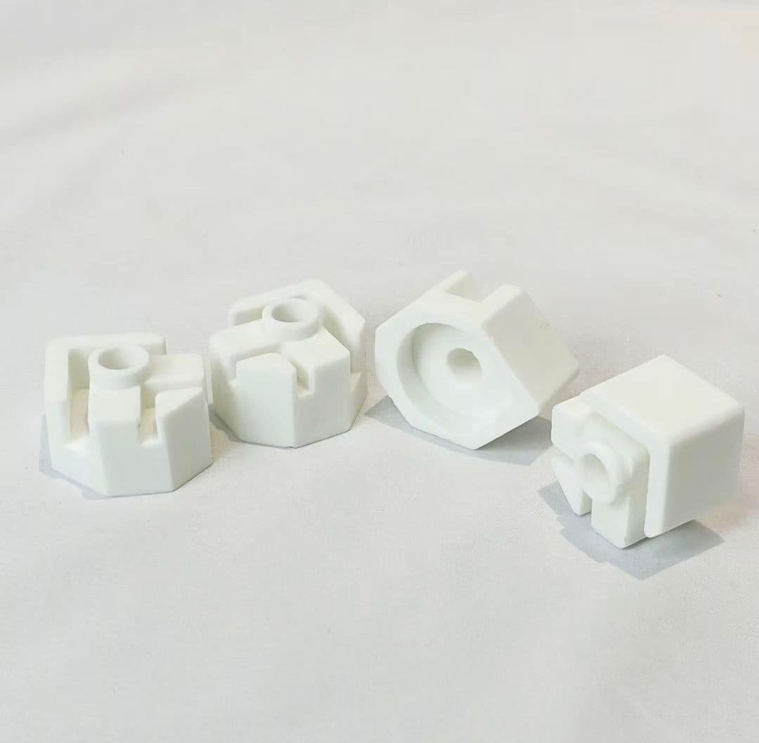
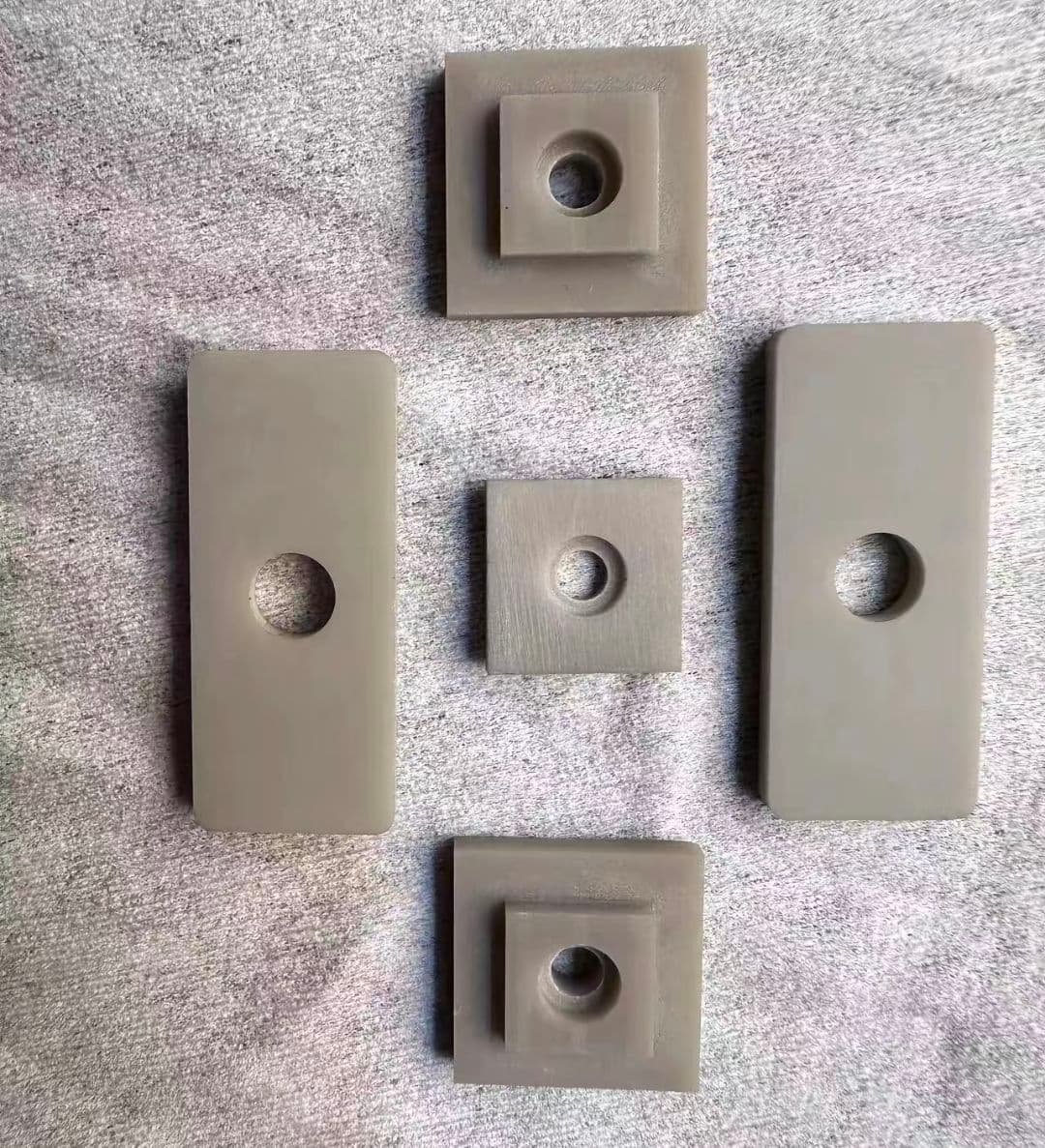
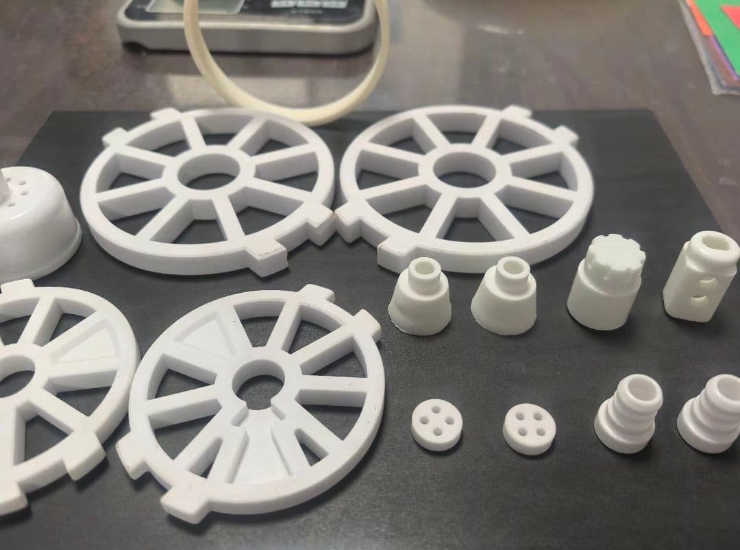
Ceramic Insulator Forms for Your Assembly
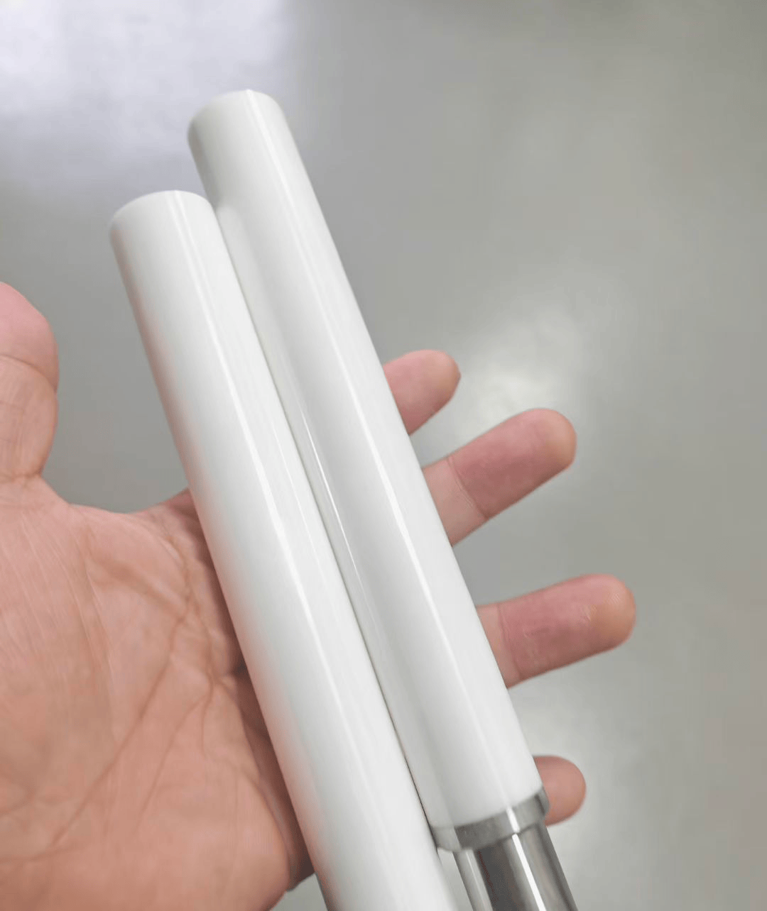
Ceramic Insulator Pins and Stand-Offs
Pins and stand-offs can be reviewed for spacing, support, routing or isolation duties, with diameter, length, end geometry, mounting method, surface condition and assembly loads defined on the drawing.
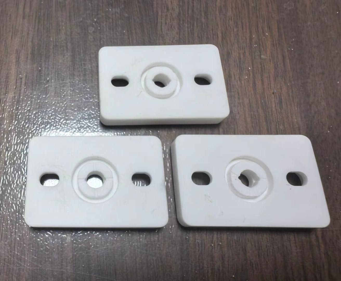
Ceramic Insulator Plates and Discs
Plates and discs can support separation, mounting or barrier functions. Review thickness, flatness, holes, edge treatment, clamping loads, thermal conditions and contact surfaces before selecting material and process.
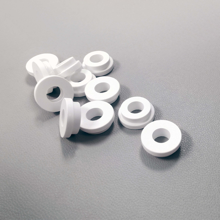
Ceramic Insulator Rings and Washers
Rings and washers can be developed around clearance, spacing, sealing-adjacent or fastening interfaces. Define inner and outer geometry, faces, edge condition, compression, temperature and inspection access.
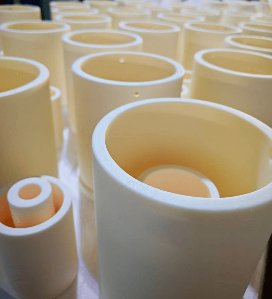
Ceramic Insulator Tubes and Bushings
Tubes and bushings can be assessed for conductor passage, isolation, support or protective duties. The RFQ should identify bore geometry, wall sections, end features, mating parts, environment and dimensional controls.
C-CERAMIC Manufacturing Capabilities
C-CERAMIC exists to help industrial teams turn demanding ceramic part requirements into production-ready components. Our ceramic manufacturing capabilities bring material and design review, mold making, forming, high-temperature sintering, machining, finishing and inspection into one coordinated engineering workflow.
From silicon carbide, zirconia, alumina and silicon nitride components to project-specific technical ceramic selections, we support prototypes, low-volume runs and scalable production. Our platform includes ceramic injection molding, precision grinding, lapping, CNC ceramic machining and final dimensional inspection for parts built around real operating conditions.
What differentiates C-CERAMIC is continuity from the first drawing through contract manufacturing. Engineering, process selection and finishing are aligned around the same component requirements, helping OEM, R&D and procurement teams source pins, seals, plates, tubes, nozzles and other custom ceramic parts with a clear path to production.
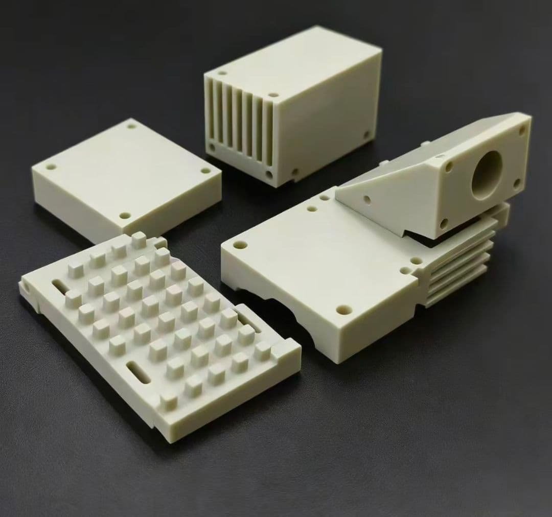
A Practical Guide to Sourcing Ceramic Insulators
Define the Insulator Duty and Assembly
Start with the function the ceramic insulator must perform in the assembly. Identify whether it separates conductors, supports a terminal, maintains spacing, guides a component, protects a passage or combines electrical and mechanical duties. Record the operating temperature, cycling pattern, surrounding atmosphere, contacted chemicals, moisture or cleaning exposure, mechanical loads, clamping method and any movement or vibration. Explain which surfaces touch metal, polymer, fluid or another ceramic, because interface behavior can influence material and finishing decisions. A clear drawing should show datums, bores, shoulders, grooves, radii, edge breaks, mounting features and the orientation used during assembly. Distinguish critical dimensions from reference dimensions, and identify surfaces where chipping, roughness, flatness or cleanliness could affect installation. If the application involves high voltage or another regulated duty, provide the applicable internal design criteria and test expectations without assuming that a general ceramic description proves compliance. C-CERAMIC can then review the part as an engineered insulator rather than a generic ceramic shape. Include expected annual or batch quantity, prototype needs and packaging or handling concerns so the proposed route reflects the complete procurement requirement.
Select Material and Compatible Interfaces
Material selection for ceramic insulators should follow the complete duty, not a preferred grade listed in isolation. Alumina may be a practical starting point for many electrical separation and support geometries, while zirconia, silicon carbide or silicon nitride may be reviewed when mechanical, wear, thermal or chemical demands change the balance. The correct choice depends on the specific material condition, geometry, firing route, finish, interfaces and acceptance criteria. Ask how the proposed ceramic will interact with conductors, fasteners, brazed or clamped parts, seals, adhesives and neighboring metals. Differences in thermal expansion, contact pressure, edge loading and assembly preload can create risks even when the ceramic itself appears suitable. Provide temperature ranges and cycling information, but avoid treating an unverified numerical property as a design guarantee. State whether the component must remain electrically isolating under a defined environment and what internal validation is required. Surface condition matters at mounting faces, bores, sealing-adjacent areas and locations exposed to contamination or abrasion. A useful quotation should identify the proposed material family, assumptions, alternative options and unresolved compatibility questions. Final approval should follow drawing review and application-specific qualification, not a stock material label.
Review Geometry and Manufacturing Routes
Ceramic insulator geometry determines how much of the route should be formed, sintered and machined. Simple rings, washers, discs or stand-offs may be assessed differently from thin-wall bushings, stepped tubes, slotted bodies or parts with intersecting holes. Review wall sections, radii, unsupported projections, sharp internal corners, deep bores, access for finishing and the locations of assembly loads before choosing a process. Ceramic injection molding may be considered for repeat quantities and suitable complex shapes, but tooling, feedstock behavior, shrinkage, wall balance and post-sinter operations need review. Other forming methods may be more appropriate for prototypes, low volumes or geometry that does not justify dedicated tooling. After sintering, CNC machining, grinding or lapping can be assessed for holes, shoulders, mounting faces, flatness-related surfaces and other critical features. Define which dimensions are controlled in the formed condition and which require post-sinter finishing. Ask the supplier to identify distortion, chipping, edge damage, inaccessible features and datum-transfer risks. A credible route review should connect geometry, quantity, material, tolerances, surface requirements and inspection access. It should also explain which assumptions must be confirmed with a prototype before repeat production.
Set Inspection and Acceptance Criteria
Inspection requirements should be written around the insulator’s assembly function. Mark the dimensions that control spacing, conductor clearance, bore fit, mounting position, clamping contact, sealing-adjacent geometry or alignment. Define datums and measurement references clearly, especially where fired ceramic shrinkage or post-sinter machining changes how the part is located. Include surface requirements for faces, bores, grooves, edges and areas that may experience contact pressure. State the acceptable treatment of chips, cracks, warpage, discoloration, contamination and other visual conditions rather than leaving judgment entirely to a generic final check. If electrical testing, dielectric evaluation or another application-specific check is required, specify the method, sample basis and acceptance logic through your own engineering standard. Do not assume that general ceramic capability statements establish compliance for a particular voltage or regulated use. Request agreement on inspection records, sample approval, traceability expectations and the characteristics to be reported before production starts. C-CERAMIC can review dimensional and final quality inspection as part of the route, but the exact evidence scope, measurement method and documentation should be confirmed per project. Prototype inspection should be planned to reveal assembly risks before the production quantity is released.
Compare Prototype and Production Quotations
Prototype and production quotations should be compared on more than unit price. Ask whether each quotation includes material review, tooling, forming, sintering, machining, grinding, lapping, inspection, packing and any one-time engineering activity. A prototype route may use flexible methods or limited tooling to test fit and critical features, while a repeat-production route may justify dedicated mold development or ceramic injection molding. These routes can have different cost structures, dimensional assumptions and transition risks. Confirm whether quoted quantities refer to trials, accepted parts, production lots or forecast demand. Request the assumptions behind tolerances, shrinkage allowances, finishing operations, inspection scope and rejected-part treatment. Check whether the same material condition and surface requirements are maintained between prototype and production, or whether a change requires requalification. Lead time and delivery should be confirmed after drawing and process review rather than inferred from a general capability statement. Ask how changes to geometry, quantity, material or inspection evidence would affect the quotation. A useful comparison identifies non-recurring tooling, recurring processing, sampling, documentation and packaging separately. It should also show which items remain conditional because feasibility has not yet been demonstrated.
Prepare a Complete RFQ and Qualification Plan
A strong ceramic insulator RFQ gives the supplier enough information to evaluate function, process and evidence together. Include the latest drawing revision, model if available, material preference, application description, electrical role, temperature, environment, mechanical loads, mating components, assembly method, quantity by phase and expected repeat demand. Mark critical dimensions, datum references, surfaces, edges, holes, bores and interfaces that require special attention. State inspection reports, visual criteria, sampling, packaging, identification and documentation expectations without requesting unsupported certifications. Ask for the proposed material family, manufacturing route, tooling assumptions, post-sinter operations, inspection approach, unresolved risks and any alternatives. Define how prototypes will be judged: fit, assembly, critical dimensions, surface condition, handling, electrical function or another project-specific requirement. Establish who approves drawing changes and what evidence is needed before production release. If a regulated or high-energy application is involved, provide the applicable customer or internal standards for review; do not assume a supplier page proves compliance. Finally, request confirmation of MOQ, lead time and capacity for the specific project because these details are not universal. This structure helps procurement compare offers on technical completeness and qualification risk, not price alone.